The basic definition of network is a system of links (or channels) that interconnect nodes (or peer entities) in order to move information between them.
Obviously lots of different networks but we will largely speak about the internet.
- Ties together 20,000+ ISP networks
- Uses the IP protocol to do the tying of different networks.
- It is bloody huge, with a huge range of technologies involved
- We know all of the other problems (failures, trust etc)
Bandwitch/Capacity - is the width of the link, number of bits and sent/received per unit time (bits per second)
Latency/Delay - is the 'length' of the link, propogation time to travel along the link (seconds)
Bandwidth Delay Product - is the 'volume' of the link, amount of data that can be in flight at a time (undefined, bits)
It gives the maximum amount of data that can be transmitted by the sender at a given time before waiting for acknowledgment: it is the maximum amount of unacknowledged data.
Packet delay - time it takes for an entire packet to travel from A to B.
Packet Delay = Transmission Delay + Propogation Delay = (Packet Size/ Bandwidth) [How long it takes us to put the independent packet in the link] + Link Latency [How long it takes 1 bit to travel a link]
Jitter: is the variation in the time between data packets arriving, caused by network congestion, or route changes
Pipe View: Diagramatic view of packets in a link
>
- y: Bandwidth, x: Time
- <img src="/notes/typora-user-images/Screenshot 2021-01-22 at 17.51.53.webp" alt="Screenshot 2021-01-22 at 17.51.53" style="zoom:50%;" />
- Top Bracket: Packet transmission time
- Arrow: A packet, a unit of data to make transmission 'easier'
- The length of the pipe indicates its latency.
But it isn't that easy, we can't have EVERY node having a direct link to EVERY other node, so we need some smarts - switched networks. We have a box (a switch) sitting in our graph moving the data around.
Circuit switching - a source node reserves capacity along a path to the destination node, it then has sole use of the link so ends data when it wants and tears down the link at the end. This can be improved with:
Frequency Division Multiplexing ( means sharing physical resource) - users have less bandwidth because they split the channel into multiple frequencies (radio stations)
Time Division Multiplexing - users have full bandwidth, but can only transmit at certain points (their slot). Time is divided into frames (a full sequence of senders) which go into slots (each sender has one slot):
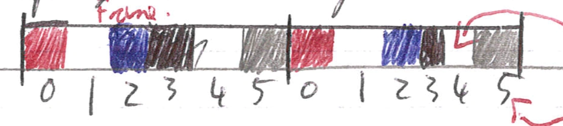
x: Sots
Top arrow: empty slots are wasted capacity
Bottom arrow: slots are at recurring time.
😊 guaranted performance + fast transfers over dedicated link
😔 wastes bandwidth if traffic is bursty (not a continuous stream, send-wait-send...)
😔 connnection setup (reserve and teardown) is overhead for small changes
😔 recovery from failure is slow as it needs to RESERVE a new link if the current one dies
eg POTS: Plain Old Telephone System
Packet switching - data is sent as chunks (packets) with a header (telling the network what to do with the packet) and a payload (data). We then get switches to forward packets to the 'right' place to go based on their forwarding table.
Connectionless assumptions of a packet-network (packet goes out automatically without determing whether the receiver is ready, or even whether a receiver exists)
We almost always assume switches are store and forward so they receive a packet in full before sending it on (this means we can use checksums etc).
The other option would be cut through switch which sends as data comes in (as the header comes first and tells us where next) BUT this is rarely used.
We don't reserve link capacity in advance so we leverage statistical multiplexing - means we can have multiple links sending data and we can handle it. Because:
we share our link OVER TIME, but data is transmitted based on demand rather than predetermined time step.
When data is there to be sent we send it. This works pretty well when traffic is bursty (connections sending at different times).
But at some point we will get data in from two places, at which point we get transient overload and we use a queue/buffer to store packets while we wait to be able to send them the buffer absorbs changing rate of transmission.
However with persistent overload we will fill the buffer and end up dropping packets.
This queuing means we have queuing delay caused by packet interference (when the network is busy our packet goes slower)
- Our key number is undefined: L is packet length, a: average packet arrival rate, R: bandwidth = Traffic intensity
- Traffic intensity approx 0 undefined small queuing delay
- Traffic intensity closest to 1 undefined large queuing delay
- Traffic intensity > 1 undefined infinite queuy delay (drop packets) as more data arriving that can be handled
😊 Pretty much all the cons of circuit switching: no wasted bandwidth, no setup overhead, resilient
😔 No guaranteed performance due to queuing delays
😔 Send extra information (headers)
Circuit switching: has a set number of max users simultaneously (total link size / bandwidth per person needed), so even if users barely need a link, they still stop other people using it.
Packet switching - has no set maximum, but we can calculate the probability of the link being overloaded:
Using a binomial distribution: n is number of users we WANT. p is probability of user being active at any time.
Overloaded number (k): number of users who would have to be active to overload network
undefined
The activity chance follows the law of large numbers (we have a big enough sample). The central limit theorem is valid aka the traffic characteristics are normal. ON-OFF periods are normally distributed
Bursts of traffic activity, packet-bursts, similtaneous bursts of traffic exhibit heavy-tails and are not normal.
Results in RTT computation that provides a smooth, continuous response.
Traffic may be synchronised – either overtly (router-update example) or accidently (packet loss at the same buffer. (Each users being active is independent.)
creating synchronised loss and retransmission events where the flows themselves are not independent.
Centralised multiplexing
coordinating how the different nodes share the physical resource with knowledge of flows, e.g. queue lengths (for variable-rate flows) and priorities, can maximise channel usage (consider static real-time scheduling)
also no latency when making a centralised (local) decision (compared to CSMA/CD when we might need to retry).
however requires a centralised scheduler - a central “point of decision” having both control over multiplexing and the required flow-specific knowledge
The internet has tier of ISP's
- Tier 3 and Local ISP's - these are the last hop of bits in the network, they are customers of the higher tier ISP's.
- Tier 2 - these are regional and are customers of Tier 1, but also do peer-to-peer with each other privately.
- Tier 1 - the backbone of the internet which have wires worldwide.
How to build an internet cake
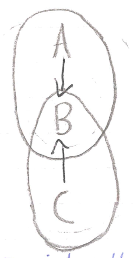
We use the concept of abstraction to split the internet (just a big computer system) into modules, unsuprisingly there are positives and negatives. We say we divide the system into layers where:
Interaction only happens between adjacent layers (in the same system)
Bottom layer is physical media
Top layer is application
Entities (a layer in one system) communicates with its peer entities, this is supported by the layers below it.
OSI Model
Application: The thing
Presentation: Allow applications to interpret meaning of data (encrypt, compress).
Session: Tracks dialog between computers as sessions
Transport: (Un..) reliable transport
Network: Best effort global packet delivery
Data link: Best effort local packet delivery
Physical: Physical transfer of bits
Actual Internet: {from OSI}
Application {Application/Presentation/Session}: SMTP/HTTP/DNS
Transport {Transport}: TCP/UDP
Network {Network}: IPv4, IPv6
Data link {Data link}: Ethernet, 802.11
Physical {Physical}: Copper, Fiber, Radio
We implement layering via embedding:
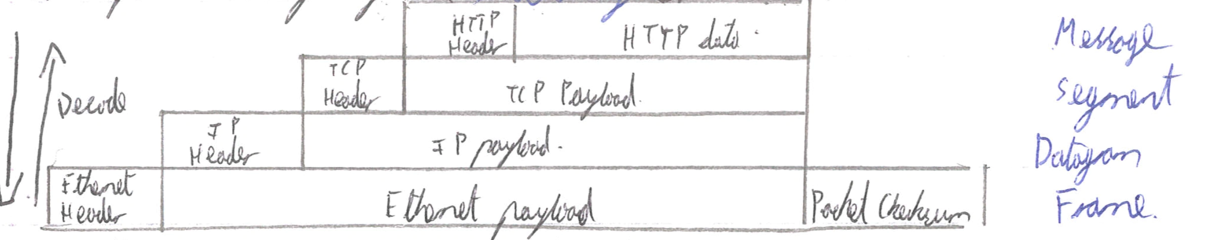
Basically high-layer info is embedded with lower layer info.
We can partly decode in transit to figure out something in the switch/router.
In these layers we have protocols, we say that in order for entities to communicate they must speak the same protocol (& version number). So the protocols are standardized, so that this can happen. The intermediate layers between application and physical layers gives us abstractions to make life easier.
😊
Modularity hides underlying detail/complexity
Innovation in different layers can proceed in parralel.
Applications only need to understand a couple (TCP, UDP) of transport mechanisms to work.
Networks using different lower-level protocols can communicate (primarily with IP)
😔
Layers may duplicate functionality
There are layer violations (layers doing too much) when gains are large (TCP-over-wireless) or when no trust (Firewall)
Information hiding can hurt performance: TCP doesn't get get told WHY a packet was lost: corruption vs congestion.
Headers can get bigggg.
But overall the layering approach is the reason the internet exists
End-to-end principle is massively cited/debated but broadly means that implementing functionality IN the network does not mean we don't do the work in the ENDS as well. There are two interpretations from this:
Only if sufficient - only implement functionality at lower levels if it can be completely implemented at this level:
if we can stop the hosts doing work at a lower level, then do so, but if host will still have to do work then DONT.
Only if necessary - Don't implement anything in the network that can be implemented correctly by the hosts. We make the network layer minimal so the system remains more flexible.
Only if useful - Only implement functionality at a lower layer if there is performance enhancements when using the functionality AND when applications don't use it.
End-to-end vs hop-by-hop
hop-by-hop, do everything at every hop
hop-by-hop encipherment is a necessary but insufficient condition for safe/secure data
hop-by-hop can not ensure a web-page will not be intercepted however wifi security modes such as WEP/WPA/WPA2 help - as does 802.1x by ensuring all traffic (in wireless) is enciphered at least in the wireless/eduroam domain, thereby preventing trivial interception.
end to end do as little as necessary in the network - push functionality to the ends.
end-to-end ensures secure carriage between client and server; however it removes the ability for the network to optimise carriage (no caches work)
end-to-end is expensive but can ensure your website order / credit card is not readable from any intermediate systems.
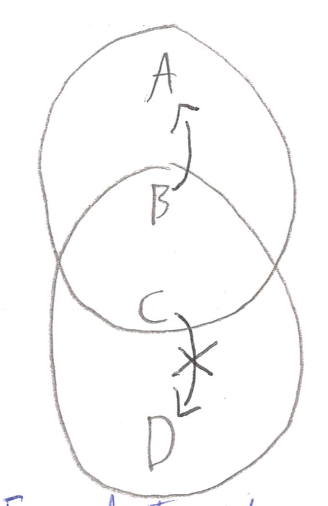
Makeup of a network:
Hosts - implement the full stack, they are bits on the wire all the way to the application layer.
Router - participate in global delivery, so must read up to the IP layer to know what switch to head to next.
They don't support reliable delivery as they have do nothing with Transport Layer.
Switches - only participate in local delivery, so read the data link layer to find the next switch to send to.
There are alternatives to standardisation eg C:
>
- Only have one implementation of the thing, and everyone use it e.g. Java
- Have open-source projects to create the implementation e.g. Python
- Sole-sourced implementation.
The Data Link Layer: Layer 2
Where a packet is called a frame, which encapsulates a datagram by adding a head & a trailer. It gives:
Physical addressing
Reliable delivery between adjacent nodes
Flow control
Error Control
Access control
We implement the link layer in adaptors or Network Interface Cards; which attach into the host system.
Line coding
Is how we convert binary to voltage patterns:
Non-Return-To-Zero: the simplest technique forces high if 1 and low if 0
😔 Long stream of 0's/1's causes baseline wander
we measure what is 0/1 from an average of the signal, so with lots of a signal value our baseline changes
😔 Long stream of 0's/1's causes clock drift
we haven't got enough transisitions to resync/recover the clock
Non-Return-to-Zero-Mark: a 1 causes a transition (from either direction), 0 means do nothing
Non-Return-to-Zero-Inverted: same as NRZM but transitions exactly on the 1 (in the middle of the signal being held).
Differential Manchester: use a clock and XOR NRZ and clock together, where each clock cycle is 1 bit (full up and down)
😔 Our bit-rate (rate of actual data transfer) is half our Baud rate (number of hi/lo's sent) as we sent two levels per 0/1
NRZM/I has the same problem as NRZ wtih clock drift as we could still see few transitions, so we use block coding to make sure there are always some exchanges (not lines of 0's or 1's). We turn any 4 bit symbol into a 5 bit symbol with a magic table, then code that with line coding. This is most commonly used as 8b/10b codec so every byte is turned into a 10 bit string with transitions to then be coded.
This could also be done with line code scrambling statistically (to get lots of 0's/1's) choose a string of bits which both parties know, then XOR it with the data before sending. XOR is symmetric so we XOR the sent data to get the actual data.
Note this doesn't provide secrecy but can be combined with block coding to give the idea of framing (start/end of a frame)
Perfect signal do not exist: problems cause bits to flip:
Attenuation - loss of energy in signal
Distortion - signal has its form changed
Noise - all sorts of different noise
We send symbols on the wire which represents data. Normally we just have hi/lo for 1/0 but we can increase the number of symbols using quad level code (0, undefined, undefined, 1) corresponds to 00, 01, 10, 11), this could increase our bit rate (data transfer speed) if our baud rate (symbol transfer speed) stays constant.
Error detection
add a parity bit - every undefined bits we add a parity bit such that there is an even number of 1's present, then when receiving we spot errors when there is an odd number of 1's
😔 doesn't work for two-bit errors; to make it sueful we need a lot of extra bits
cyclic redundancy check - every undefined bits we add a CRC(undefined)
😊 can detect multi-bit errors
😔 doesn't fix errors
Action: For both of these we can detect errors then ask the sender-to-send again
Error correction
Parity bit grid - sort the bits in a grid, have parity bits for each column AND row, then for single bit error, we find the problem bit as one column and row will both be wrong.
Forward error correction - assign only some bit sequences as valid (as far away from each other as possible) then when we get a 'bad bit sequence' find its closest error-free data (where distance is number of bits needing to change) and fix it.
Multiple access protocol
An algorithm distributed across nodes to decided how they share (the medium - eg WiFi or Ethernet), and where the medium is their ONLY coordination method. (example was CDMA)
Ideal Protocol:
when one node wants to transmit its ends at rate undefined
when undefined nodes want to transmit each sends at rate undefined.
Fully decentralised so no clocks etc
Channel partitioning:
Time Division Multiplexing and/or Frequency Division Multiplxesing but now called Time Division Multiple Access & Frequency Division MA.
😔 we get wasted bandwidth/time 😊 is fair
CMDA: Code Division Multiple Access
This is another multiplxing scheme which is used in shared mediums (3G etc)
We assign a unique code/chipping sequence (must be orthogonal) to each user, and each user encodes their data by XOR'ing the chipping sequence with the data. Decoding is then the opposite.
The technique allows for multiple users to transmit simultaneously on the same frequency.
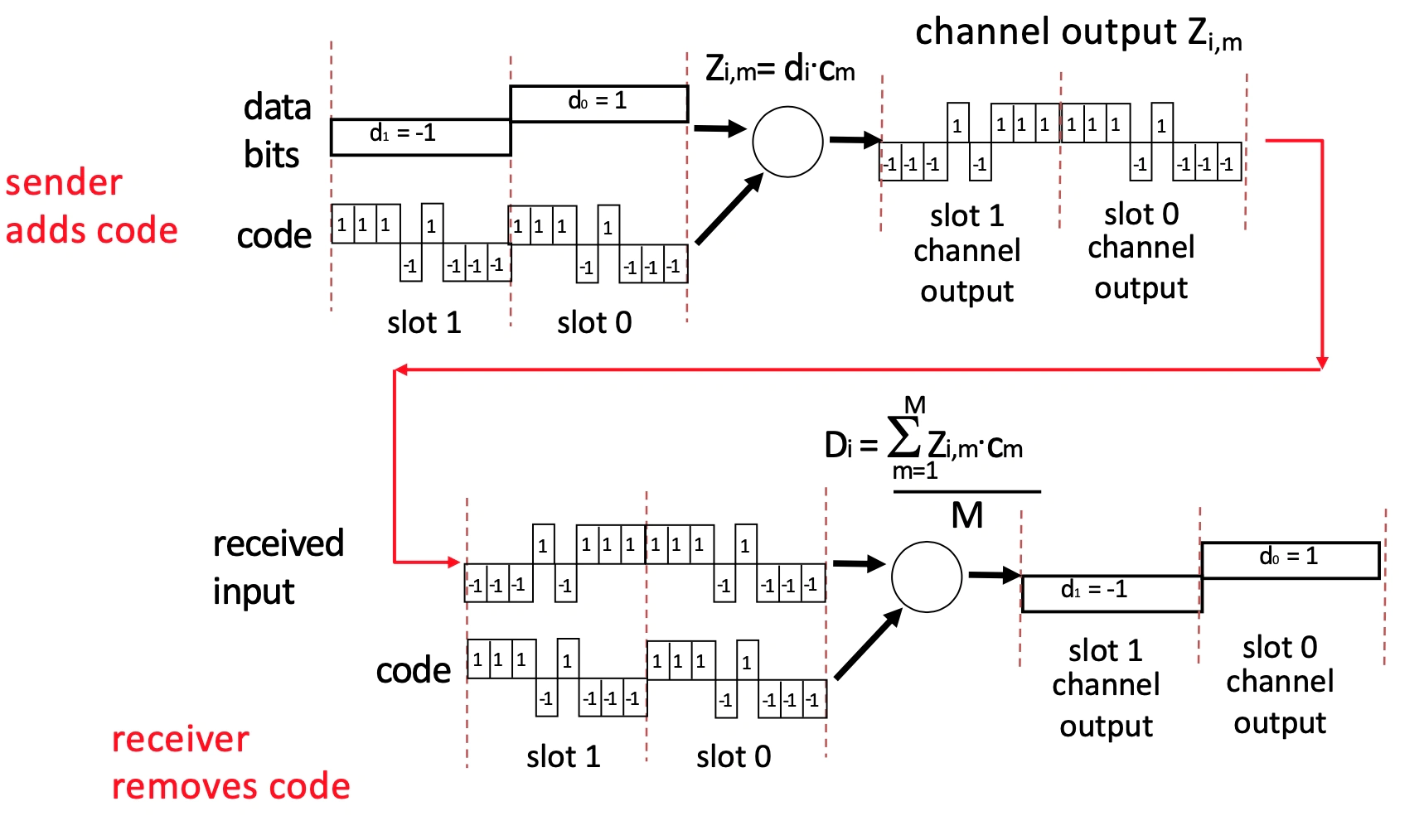
What does the data look like?
How is data bit and code combined?
How is channel output decoded?
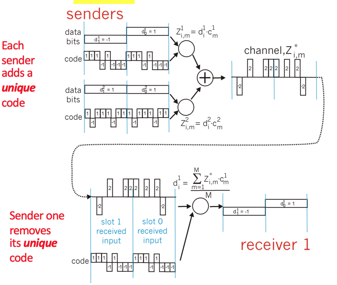
How does it work with the multiple senders and single channel link ?
How does decoding differ?
Taking turns (Bluetooth, IBM Token Ring)
Polling - some master invites shares to submit data, and they do. The master polls the slaves.
😔 Polling overhead + lots of latency - single point of failure
Token passing - we pass a control token around, saying who's allowed to speak at any moment
😔 Token overhead + lots of latency + single point of failure (from losing token)
😊 gives bounded latency
Asynchronous Transfer Mode - we have slots like Time Division MA, but anyone can send at any time, they just attach 'who they are' as a header
😃 variant of packet switching
😔 virtual circuits need setting up undefined OVERHEAD
Random access - basic concept is when node has packet send it, when there are multiple nodes transmitting stop & wait.
we are broadcasting rather than point-to-point so can get collisions when a node is trying to receive multiple signals simultaneously -> neither signal gets heard.
Needs three ideas:
Carrier sense - listen before sending and don't interrupt if channel is busy
Collision detection - if two users start simultaneously stop and have another go later.
Randomness - determine the later in some random fashion, so you don't re-collide.
Chosen solution in wired connections is: Carrier Sense Multiple Access/Collision Detection (CSMA/CD)
We encorporate carrier sense and collision detection together
carrier sense isn't enough due to propogation delay
this is easy in wired connections but hard in wireless
When a collision is detected we STOP and try again later this avoids wasted time in garbage signals.
😔 the time for collisions to be detected can be upto undefined where undefined is time to travel between nodes, this can waste a LOT of time
performance (efficency): Time spent transmitting packets undefined Total time
undefined: packet size
undefined: bandwidth
undefined: constant about how many collisions
undefined: distance between two nodes
so large packets, small distances undefined performance undefined 1
but when we increase bandwidth undefined network 'fully used' less
because of this equation high speed networks have switches to REDUCE undefined.
The random access bit is done with: exponential backoff, after m^th^ collision:
choose k randomly from {0, ..., 2^m^ - 1}
wait (K \* slot size) before trying again.
min packet size used as slot
Ethernet Frame Format
A lot of what we've been speaking about is encorporated into some version of Ethernet it can be used on all sorts of cables, network setups and medias. The exact thing that is implemented depends on version but the common attributes:
Preamble: white noise to synchronise clocks
Destination MAC address: 48 bit addresses has no 'proper' structure, but are globally unique (probably) and don't normally change
Source MAC address
Type
Payload
CRC: error detection
Pairs of twisted cabling is a single connection. (coaxial/fibre)
802.11 (WiFi)
The basic idea is that we have access points set to a specific channel, which broadcast their Service Set ID (SSID) and MAC address periodically. Then hosts scan for access points and send them stuff.
One of our key problems is that collisision detection is really hard, because we can't listen and send simultaneously and a sender signal is far less likely ot be correct.
If we try and do normal collision detection we have two problems:
Hidden Terminals
A is hidden from C so neither realises they have caused a collission at B.
Exposed Terminals
C sees that B is sending to A, so decides not to send to D, even though it could do.
Key issues are:
There is no concept of a global collision; everyone reaches different people.
Collisions occur at the receiver not the sender and we only care about what receiver can hear not sender.
Wireless CSMA - (collision avoidance)
CA (collision avoidance):
Our carrier sense is still similar to collision detection, if the medium is busy wait a random time) rather than keep checking) but other than that no change.
We infer collisions from the (lack of) receipt of an ACK from a receiver.
On collisions we use exponential backoff to adapt contention window (avoid having contention again)
😊 Fairly low latency and little wasted bandwidth with low collision probability
😔 doesn't work well with hidden terminals still
when the hidden terminal sees an ACK it doesn't know if transmission is done.
RTS/CST:
Method
Sender sends a Request to Send frame with the length of the transmission
Receiver responds with a Clear to Sender frame
Sender sends data
Receiver sends an ACK
Situations
When sender doesn't get CTS back, assume collision and backoff
If a node hears RTS, but not CTS - send data as the relevant receiver is not in range of our node, so can send
If a node hears a CTS - stay quiet until you hear an ACK
😊 good for high-traffic Access Points and helps with hidden terminals problem
😔 slower than standard CA (but could be turned off dynamically).
Channels: another technique for avoiding wireless collisions
split our frequency band into channels which don't interfere with each other
so two nodes in some range won't interfer with each other (if they choose different channels).
For Wifi:
we split into 14 overlapping channels, but there are 3 completely separate channels - 1, 6, 11.
but other technologies already share some of WiFi's frequency space so cause interference eg Zigbee.
The hardware: behind the data link layer
Hubs - dumb physical repeater; bits come in from one node and hub sends out bits to everyone else. NOTHING SMART, no CD etc.
Switch - smart link layer device takes active role and selectively forwards frames to correct place based on MAC address and Switch Table.
They are transparent (hosts unaware of presence) and self-learning (they figure out MAC addresses as they go)
It allows us to connect different physical media as it needs to do conversions between different media protocols.
Our aim is to make a switch table with each entry containing
MAC address of host
Interface number to reach host: which 'wire' to send stuff down
Time to Live: how long entry lives
Approach
Firstly we say that EVERY packet received we record MAC address and interface number.
Then to find new MAC addressses we flood "who's MAC address is this?"
Wait for a response
😊 this works with connected swtiches as well, so every switch has a table of the next step for ALL hosts.
😔 problems when we have loops!
Solution: to loop problem!
create a spanning tree: a sub graph connecting each vertex WITHOUT ANY LOOPs, if a link is not in spanning tree, we won't use it.
Each switch determines if each interface is on the shortest path from the root i.e not in the spanning tree.
distributed minimum spanning tree algorithm:
send messages of form (Y, d, x)
Y: proposed root
d: distance to root
x: node message came from
everyone proposes themselves as root: (X, 0, X)
arbitrarily decide root based on lowest ID
switches constantly receive messages and will change their distance (and flood everyone else) if
message has lower root ID than current choice
message has shorter distance to some root
algorithm must react to failure:
root switch periodically annoces itself as root (and propogate around tree).
other switches detect failure through timeout and claim to be root if they think failure has happened (algorithm completely starts again)
Local networks can't be too big as:
creating MST's is hard for larger networkers
every switch knows the location of every other host - BIG tables.
The Network Layer
Aim: Produce a global system with its own addresses: building on top of the data link layer - which was fundamentally LOCAL.
Router: the tech that operates on the network level.
It does two jobs at different timescales:
Forwarding
we direct a data packet to an outgoing link based only on the individual router state (a forwarding table).
this has to be very fast
Routing
we compute the paths packets will take and generate the individual router state based off of conversations with other routers.
This can afford to be slower as we shouldn't have to do this too often.
Router Capacity = N (Number of external router paths) x R (Speed/Line Rate of a port)
We normally assume ports are full duplex so routers can send & receive simultaneously along the path.
Inside our router:
Data plane
Linecards (input)
process packets on their way in and strips away ethernet frame to get bits of the (IP) packet and make forwarding decisions.
they also manage queues and each have their own foorwading table.
Interconnect Fabric
basically does what linecards want, and moves packets between linecards.
Linecards (output)
repackage packets as ethernet frames and send on its port.
Control plane
Route/Control Processor
makes decisions over a long time, it create the forwarding table and pushes it to EVERY linecard (input) simultaneously.
Routing: control plane
We split the internet into Autonomous Systems/Domains and manage routing at two levels:
Intra-Domain routing - each domain chooses its routing protocol to route packets around its own domain (each domain is controlled by one admin).
Inter-Domain routing - the common protocol to allow domains to speak to each other, we use Border Gateway Protocol (it allows companies to do as little comms as possible), but we won't cover that in this course 😃.
The actual preference becomes "whatever BGP considers best" so it may pick either solution.
Devolves a BGP routing solution problem to a Longest prefix match problem. LPM always wins.
Local, short path routes for a particular IP prefix are injected into the local BGP routes. These cause IP traffic for an address in that prefix to be routed to a locally designated destination.
Can also us Content distribution system specialist DNS – useful when there is no local datacenter.
Implement netblock filtering to restrict the size of the routing table.
The whole concept of routing protocols: is that each router calculates its own routing table by treating the network as a graph where edges have an associated "cost" (which is some number/function of distance). They want to find the last cost path from A to B.
multi homing allows devices to be on multiple networks but this increase the routing table size.
Intra-Domain routing algorithms
Link State
Each node maintains its local link state (a list of directly attached nodes + cost).
Each nodes floods its local link state, and nodes learn the global link state and forward on the information.
Each node knows the whole graph, so computes Dijsktra to find its shortest path to every other node (<u>each iteration we find one more closest neighbour, so we have to do undefined iterations!</u>) then its forwarding table comes from this info (just the first hop needing to be done).
😔 scalability
we need to send undefined messages to discover global state.
every node has an undefined (can become undefined) operation to compute Dijkstra.
Dijkstra you explore the best node possible from you're current frontier.
Keep a stack on the left to show order you explored.
our link state database in each node is undefined
we have undefined entires in our forwarding table
😔 transient disruptions
failures result in some routers knowing before others so the link-state DB is inconsistent.
this can lead to forwarding loops of nodes thinking the other is the shortest path, so goes back and forth.
Distance Vector
Every node maintains a distance vector of how far away from EVERY other node it is.
It shares this with its neighbors.
On receiving a distance vector a node compares it to their current distance vector and updates any entries that are shorter (with a note to say where to send it).
This iterative process means nodes converge to the set of shortest paths by only knowing hte NEXXT node that it needs to send to.
😔 using a non-additive metric (eg maximal capacity of link) - we get a problem with looping as the 'cost' won't necessarily change in a loop, so we keep going looking for the best.
😔 routers use different metrics - if nodes care about different things their distance state vector will have different meaning to different nodes, this is a problem.
😔 routers can lie - either on purpose or not, we can get ALL traffic going through one router because it says its next to EVERYTHING.
😔 Overall it is more vulnerable to loops
😊 It has 'good' complexities
#messages = undefined
where #iterations is ideally undefined but varies due to routing loops or the count-to-infinity problem: nodes feed each other bad information due to a failed node and distance to failed node keeps increasing.
poisoned reverse we advertise undefined to the mutual node.
processing = undefined
Metrics for routing:
Propogation delay
Congesiton
Load balance
Bandwidth (available, capacity, maximal)
Price
Reliability
Loss rate
Combinations
Message delivery types:
Broadcast: send message to everyone
Multicast: send message to all members of some group
Anycast: send message to any members of some group.
Datapath
will keep working even when control plan is broken (it will keep using most recent table update).
per-packet delay: undefined (how to speed up)
typical values
RTT is .15s and BW 100Mb/s
for a LAN link
queueing ≫ propagation ≫ transmission ≫ processing
for a Data Centre link (unusually large b/w but bound (small) RTT values)
(queueing) ≫ transmission ≫ propagation ≫ processing
absurdly low latency and large bandwidth: undefined, 10 Gb/s such that actually bandwidth delay product much lower.
implementations: some of the considerations in DCN include practical circuit-orientated networks, with the lowest layer having no switches or queues.
the cause of propagation (proportional to distance)
the cause of queueing (proportional to contention)
the cause of processing (unusual packets)
the cause of transmission (the capacity of the link)
processing delay: time required to examine a packets headers and determine where to direct the packet.
use circuit switching (however needs reservation of link etc)
simple deltas on the amount of processing per packet
can include e.g., bit-level error checking (which you could remove)
queueing delay: packets experience the queueing delay as they are stored in queues awaiting transmission onto the link. The delay depends on the amount of congestion and length of queues.
accept more occasional loss with smaller queues
range from 0 (or negligible) to undefined scale values, undefined, but use number of packets and buffer story to calculate.
transmission delay & propagation delay already discussed.
per-packet processing:
accept packet arriving on link.
lookup packet destination in forwarding table: speed-limit on the operation: a naive forwarding table for a 32 bit address would have 4 billion entries!
we group entries to keep table size small
implement Longest Prefix Match by ordering the entries from most to least specific then searching downwards. That way the first matching entry we find will be the most specfic - we should choose Cmabrdige rather than England.
Exception processing requires that a packet be sent to a control processor causing significant additional delay - the control plane much slower and will also take up transfer time.
manipulate packet header eg decrement Time to Live
send packet to outgoing port.
buffer packet in the queue: need to decide how big to make our buffers: based a lot on TCP as this is a majority of the traffic
Rule of thumb | packets | Intuition | Assume | Evidence |
|---|---|---|---|---|
undefined | 1,000,000 | TCP Sawtooth | Single TCP Flow, 100% Util | Simulation, Emulation |
undefined | 10,000 (with flows) | Sawtooth Smoothing | Many Flows, 100% Util | Simulations, Test-bed and Real Network Experiments |
undefined | 20-50 | Non-bursty arrivals | Pace TCP, 85-90% Util | Simulations, Test-bed Experiments |
Def: T (RTT: Round trip time) - C (capacity) - W (window size)
Row 1: This is huge and present loads of problems: big buffer undefined longer queuing time as use slower DRAM.
Row 2: Can use SRAM feasibly. Basically says the peak sawtooth won't be reached by everyone simultaneously, we're more likely to have a fairly flat line.
Row 3: If access network is slower than the backbone this makes sense.
transmit packet
IPv4: the de facto transport layer for the internet
Structure
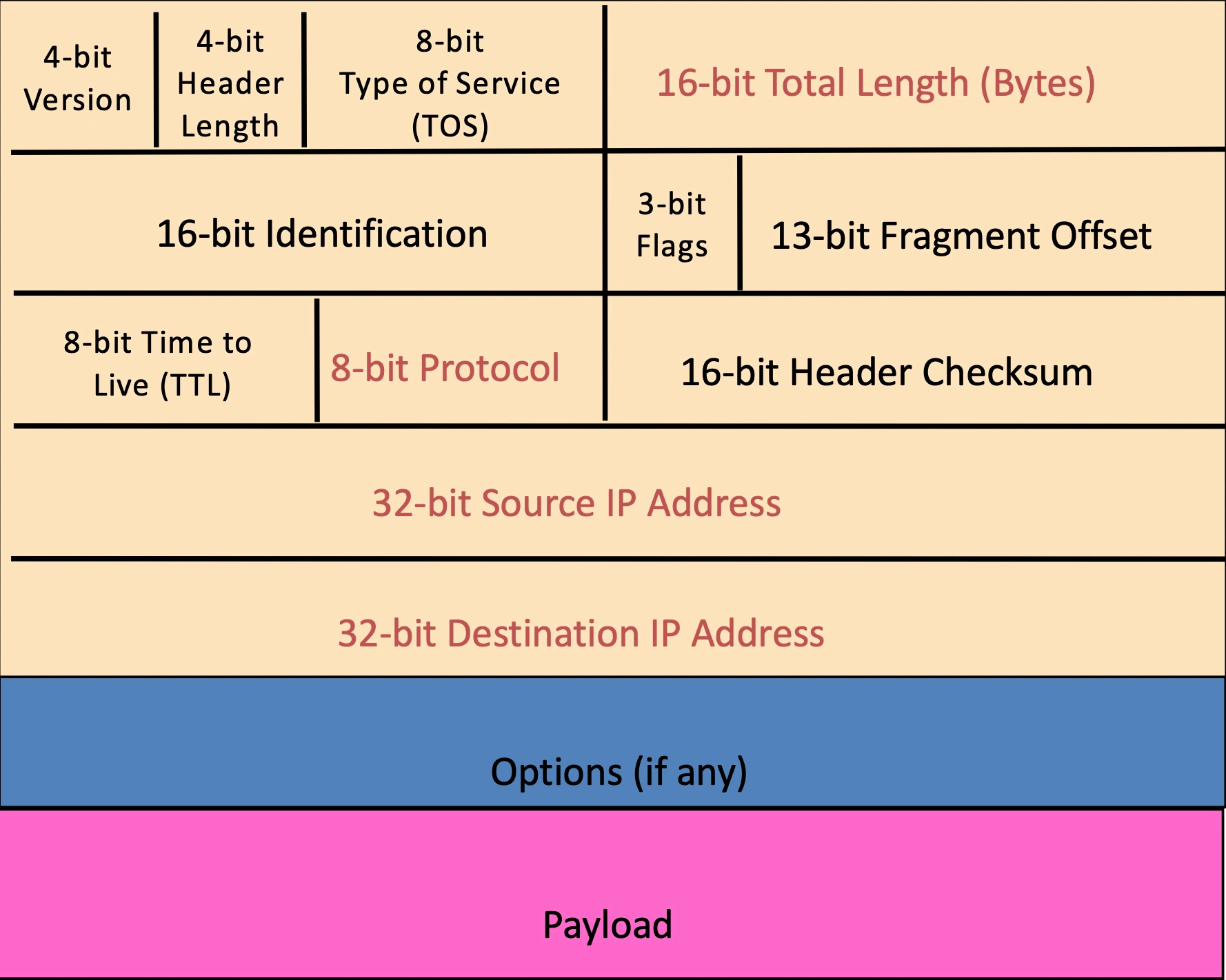
Version number: necessary so we know what else to expect
Header length: number of 32-bit words in the header typically 5
TOS: allow packets to be treated in different ways, v complex, largely ignored
Number of bytes of packet: max size in theory is (2^16^ - 1) but Ethernet frame has smaller max
2nd row: used for fragmentation if packet too big later xx.
Time To Live (TTL): Decremented at each hop and discarded if reaches 0: Time exceeded ICMP (Internet Control Message Protocol) message sent when TTL=0
Protocol: Identifies the higher level protocol: 6 is TCP; 17 is UDP
Checksum: check if the header is correct: if it is wrong router discard it. Recalculated every router.
Source: useful for reply mechanices and acceptance decisions.
Destination: get there! Allows node to make forwarding decisions
Options: asks routers to do some extra work
Fragmentation
When forwarding a packet an internet router can split it into pieces for the next hop, this is needed as network links Maximum Transfer Units - which is the largest possible data-link frame. This changes as we travel as different technologies have different capacities.
We then reassemble at the final destination, even if fragmented multiple times.
Structure:
The identifier (16 bits) are used to tell which fragments belong together.
The flags (3 bits) have:
Reserved (RF)
Don't Fragment (DF) - tells routers to not fragment, they instead DROP the packet and send back "Too large" ICMP message.
More (MF) - says that this fragment isn't the last one from the original packet.
The offset (13 bits) is used to say which part of the original datagram the fragment covers in 8 byte units.
Addressing
An IP address is 32 bits long in the form 128.12.3.244.
We assign an address to each interface (connection between computer and physical link).
Generally hosts have one interface, whereas routers have multiple.
Subnets are groups of interfaces
the first part of the IP address is the subnet part
the second part is host part
/24 in the address: is the subnet mask: that tells us how many bits are 'subnet'.
Devices in a subnet can interface with each other without a router intervening
e.g: subnet[223.1.2].host[3]/24
We use Classless Inter-Domain Routing:
we AND the subnet mask (a bunch of 1's) with IP address to get the subnet address.
we get IP address by:
Hard coding it in a system admin file.
Dynamic Host Configuration Protocol - we dynamically ask for an IP address from a server and it gives us one.
this means a network can reuse IP addresses when computers are turned off.
the server knows addresses its allowed to allocate by being told by ISP's who get told what they can allocate by ICANN. Noe the hierarchical organisation makes routing easier in the form of adverts by ISP's saying "send me anything with addresses xxx".
special addresses:
0.0.0.0/8 - labels the current network (to be used as source address)
10.0.0.0/8 - used for local communications within a private network
127.0.0.0/8 - used for loopback addresses/localhost, connecting to itself.
192.0.0.0/24 - used for private network
20.3.2.0/24 or 20.3.0.0/16 - looks like a subnet mask is the network identifier
20.3.2.255/24 or 20.3.255.255/16 - subnet then all 1's is the broadcast address
192.108.1.1/24 or 192.108.1.254/24 - is OFTEN used as the default gateway, the IP address of the router in NAT senses.
NAT: Network Address Translation
A technique developed to avoid address exhaustion in IPv4
We allocate our local network to be the IP address range 10.0.0.0/24, and each interface gets a local address.
Then the router is given a single address to represent the whole network (this is the address the rest of the internet sees), and we identify hosts with port numbers within the packets.
Specifically for a datagram:
Outgoing datagrams replace (source IP addr, #port number) [LAN side address] with (NAT IP addr, #new source port) [WAN side address] in the router.
Remember using NAT Translation Table the translation pairs we use.
Incoming datagrams use the table to replace the destination fields in IP & TCP headers.
😊
Only one IP address needed for multiple devices: reduces address exhaustion
Can mess with our local IP addresses without telling outside world
Can change external address and internal hosts don't need any change
More security as devices aren't explictly addressable: FIREWALL
😔
Violates end-to-end principle as needs to deal with layer 4 (TCP ports)
Address shortage could be solved in other ways (IPv6)
We may want a server behind a NAT.
difficult as no prior connections to source - outside machine, must know the right port number to direct to ?
😯 statically configure NAT to designate a certain machine to a specific port
😯 universal Plug n Play allows NATted hosts to learn public IP addresses and add/remove port mappings for external access.
😯 Relay system - client talks to relay, NATted server initiates comms with relay.
ICMP: Internet Control Message Protocol
Its messages are carried in IP datagrams: they don't transmite DATA, just set messages.
Structure:
Type - Code - Checksum
Combined in an IP packet with protocol value of 1
They are sent for error reporting and echo request/reply ALL over the place.
An example use is traceroute:
send a series of UDP messages with increasing TTL's (from 1) on an unlikely port number.
when the n^th^ datagram reaches the n^th^ router TTL expires, router discards the datagram and returns an ICMP message (with router name - found with reverse lookup + IP address)
When get an ICMP message back we can calculate RTT
😔
ICMP messages sometimes follow different paths to IP packets
Discover routes at the interface level not the router level.
Sometimes routes just ignore our messages cause they don't like ICMP.
Address Resolution Protocol: sending an IP address to the right place - linking network and data link layer:
Every node maintains an ARP Table of <IP address, MAC address> pairs.
When sending a packet we consult the table, if its in there then send it.
If the IP address isn't there, we broadcast "who has this IP address\*\*" and someone responds with their MAC address, then sender caches result in table.
😔 ARP allows people to impersonate IP addresses really easily, ARP poisoning is a classic security flaw.
Example: A Sending a Packet to B
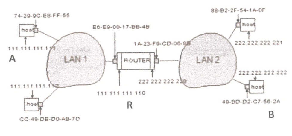
Host A constructs an IP packet to send to B
Host A has a gateway router R: this is used to reach addresses outside its subnet.
Address for R learned via DHCP/config through broadcast
Host A learns the MAC address of R's interface
ARP request & response
Host A encapsulate the packet and sends to R
Router R's adaptor receives the packet
R extracts the IP packet from Ethernet frame and reads destination
Router R consults its forwarding table
Router R's learns the MAC address of host B
ARP request & response
Router R encapsulates the packet and sends to B
IPv6: solving the unnecessary complexity of IPv4 and address exhaustion
Protocol changes
Larger Address Space - addresses 128 bits long rather than 32
Increased MTU - networks can handle far more traffic than 1970s
No enroute/in-network fragmentation - simplfies handling of packets in network, hosts are expected to do Path MTU Discovery before sending.
No checksums in IP header but REQUIRED in UDP: this is inline with the end-to-end principle.
Extension headers - are used for extensions to IPv6, they are specified with the next header number which tells us the extension OR the protocol of the next layer.
Auto-configuration
Flow-label
Replace broadcasts with multicast
Addresses Details
The basic format is 8 16-bit blocks separated by colons (4 hex digits per block). We condense representation by eliminating leading zeros and replacing ONCE a block: eg 000c... to c:d
We split them into:
Network prefix (often split into routing prefix & subnet ID) is 64 bits and used for routing a packet.
Interface identifier - is 64 bits and used for identifying a specific host on a subnet
A /64 mask routes to 2^0 subnet, /63 routes to 2^1 etc...
Reserved:
::/0 default route/specify all networks
host-local: localhost; ::1 is equivalent to 127.0.0.1
link-local: not routed: fe80::/10 is equivalent to 169.254.0.0/16
site-local: not routed globally: fc00::/7 is equivalent to 192.168.0.0/16 or 10.0.0.0/8
global unicast: 2000::/3 is basically any v4 address not reserved in some other way
multicast: ff00::/8 is equivalent to 224.0.0.0/4
Broadcasting
ping6 ff02::1 All nodes in broadcast domain
ping6 ff02::2 All routers in broadcast domain
Actual ISP numbers (example)
ISPs have 16 bits for site prefixes (from /32 to /48)
Site prefixes have 16 bits for subnet IDs (from /48 to /64)
Each interface ID has 64 bit address space
Assume privacy addresses (no 64 bit EUI-64 constraint. . . random numbers generated for arbitrary sized interface IDs)
Say the ISP keeps control of the subnet bits gives them 32 bits of customer address space
Or even takes 16 bits of the interface IDs gives them 48 bits of customer address space (256T addresses!)
The Neighbour Discovery Protocol is a subset of ICMPv6 that allows hosts to discover other hardware on the network.
A host can solicit a neighbour host to get the MAC address of the host (or check if the address is in use)
A host can solicit a router to learn about network configuration.
It knows where to send this due to a well-known multicast address.
Address assignment
The network prefix is derived from Router Advertisements (bascially they are told this by a 'higher up', which has been allocated by ICANN).
The identifier:
can use Stateless Address Auto Configuration (SLAAC): allows hosts to automatically configure/choose their addresses and learn the routes
when a host start up it decides upon a link local address, just so it can get the network prefix off of a router (or wait for a periodic router advert announcement)
once it has the network prefix it derives an Extended Unique Identifier from its MAC address (maths magic!). This is actually how it generates its unique link local address.
After router solicitation, the router knows the IP address generated belongs to that host!
😔 this has privacy concerns as the EUI-64 doesn't change over time so can be tracked around the world.
😔 embedding the MAC address in the IP address means a host's vendor is identifiable undefined bad for security.
we can use stateful DHCPv6 which is just like the old DHCP.
Transition of IPv4 to IPv6
We note that the two protocols are fundamentally incompatible, so to introduce IPv6 we need new infrastructure while keeping IPv4 working.
We use dual stacked hosts in the public internet which can handle IPv4 and IPv6: which then use only ONE of the protocols in the backend but that doesn't matter as users see the dual stacked host. You can turn off IPv6 by not showing a AAAA record.
IPv6 carries the obligation to try IPv6 before IPv4, this led to some conflicts with DNS resolution (since different from IPv4) so Happy Eyeballs (so you don't stare at the screen) was a solution which modifies application behaviour:
IPv6-only to the host but an IPv4-only app trying to access an IPv4-only service:
464XLAT: DNS64 + NAT64 + shim layer on the host itself to offer IPv4 addresses / understanding to apps.
Improvements
Have verifiable source addresses for both accountability & anonymity
Use different packet headers for the edge and the core as they do different jobs
A payment field or responsbility field for who is in charge of packet delivery (ISP's etc).
Transport Layer
Location: normally at the end - hosts.
Aim:
Multiplexing - multiple applications on one host can use the network, we need to direct packets to the correct application.
Reliable data delivery - if we just used IP, we can get packets doing all sorts and we won't necessarily have a reliable service, so the transport layer aims to give this.
Present in TCP and not NEEDED.
Paced data delivery - we want to do some pacing control so we don't overwhelm the network (or waste bandwidth).
Present in TCP and not NEEDED.
Our main two protocols:
User Datagram Protocol (UDP) a minimalist protocol on which we build everything else
Tranmission Control Protocolo (TCP) gives reliable, in-order byte stream abstraction with congestion control but no performance guarantees.
UDP:
Our application layer talks to us via sockets - software abstraction in the OS. So each application can define these sockets to put data into and take data out of it. We then have ports which are transport layer identifiers. We store a mapping between sockets and ports, and our packets contain source and destination port numbers. So when a host receives an IP packet; it combines destination IP address AND destination port number to send the TCP payload to the correct socket.
Ports are 16 bit numbers with 0-1023 having particular services on them:
SSH: 22
HTTP: 80
HTTPS: 443
Then 1024-65535 have dynamically chosen meanings they are ephemeral ports.
And that is basically all UDP has: meaning its very lightweight and adaptable, its packets (which are contained in IP packets) have:
Source port
Dest Port
Checksum
was optional in IPv4 but is now mandatory in IPv6
Length
length of UDP header + UDP payload
Reliable Data Transfer: the IP layer only gives us best effort transfer, but things can happen to packets: corrupted - lost - delayed - reordered - duplicated.
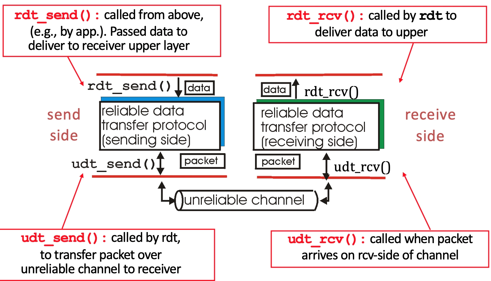
Version 1.0: assume reliable channel
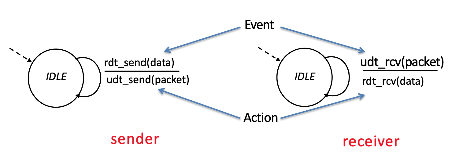
We represent the protocol with state machines.
where state means the next is uniquely determined by next event.
Version 2.0: we now consider that packets may get corrupted (and get detected with checksum) but they aren't ever lost.
We have receiver feedback so receiver can send ACK or NAK to the sender
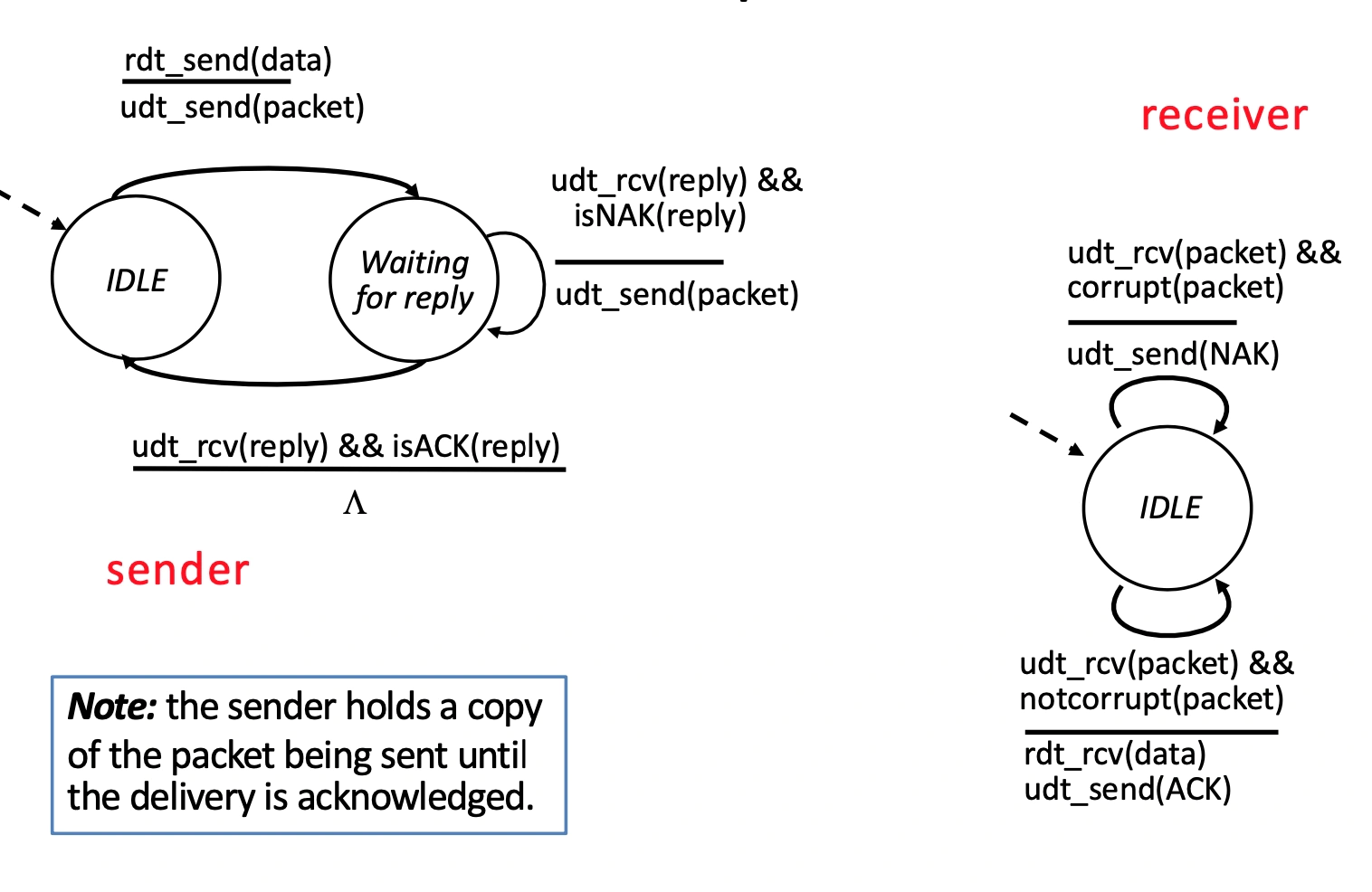
Sender:
IDLE: waiting for application to ask
Waiting: hold onto packet sent, until ACK
Receiver
Check corrupt: send ACK or NAK accordingly
But we have a problem - ACK/NAK can also get corrupted; sender doesn't know what happened at receiver and can't just retransmit: possible duplicate.
Solution - data and ACK packets carry sequence numbers and we check corruption of ACK/NAK on corrupt we resend as though it was a NAK - receiver discards (doesn't deliver) duplicate packet.
we only need 0, 1 for sequence numbers because there is only ever one outstanding message.
From this addition we can also eliminate NAK as the ACK now says the # of the last received packet and if that number is the exepcted # we are good, if not treat it as though it was NAK.
Version 3.0: we can lose packets and they can be corrupted.
We introduce timeouts at the sender, it waits a reasonable amount of time then resends packet if no ACK received.
This can lead to duplicates being received as it could be the ACK got lost, not the packet.
This is already handled with sequence numbers introduced earlier - the receiver checks if the packet has the sequence number it is expecting, if not it sends back ACK of previous number.
Performance issue: we get a bottleneck as we are waiting for EVERY packet
time to transmit packet = undefined
L: packet length
R: Bandwidth
Utilisation = time sending packets / total time = undefined.
Conceivable for undefined to be 30ms and undefined to be 0.008ms, we have A LOT of wasted time.
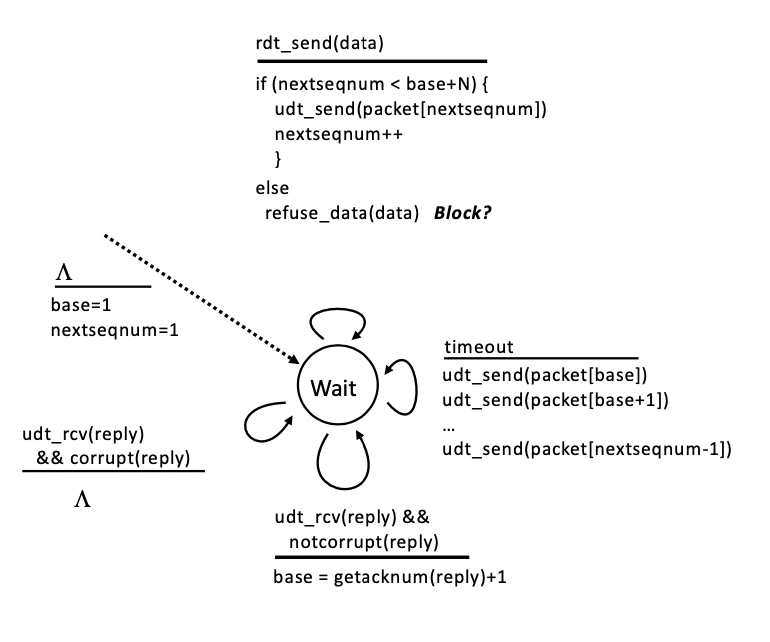
Sender:
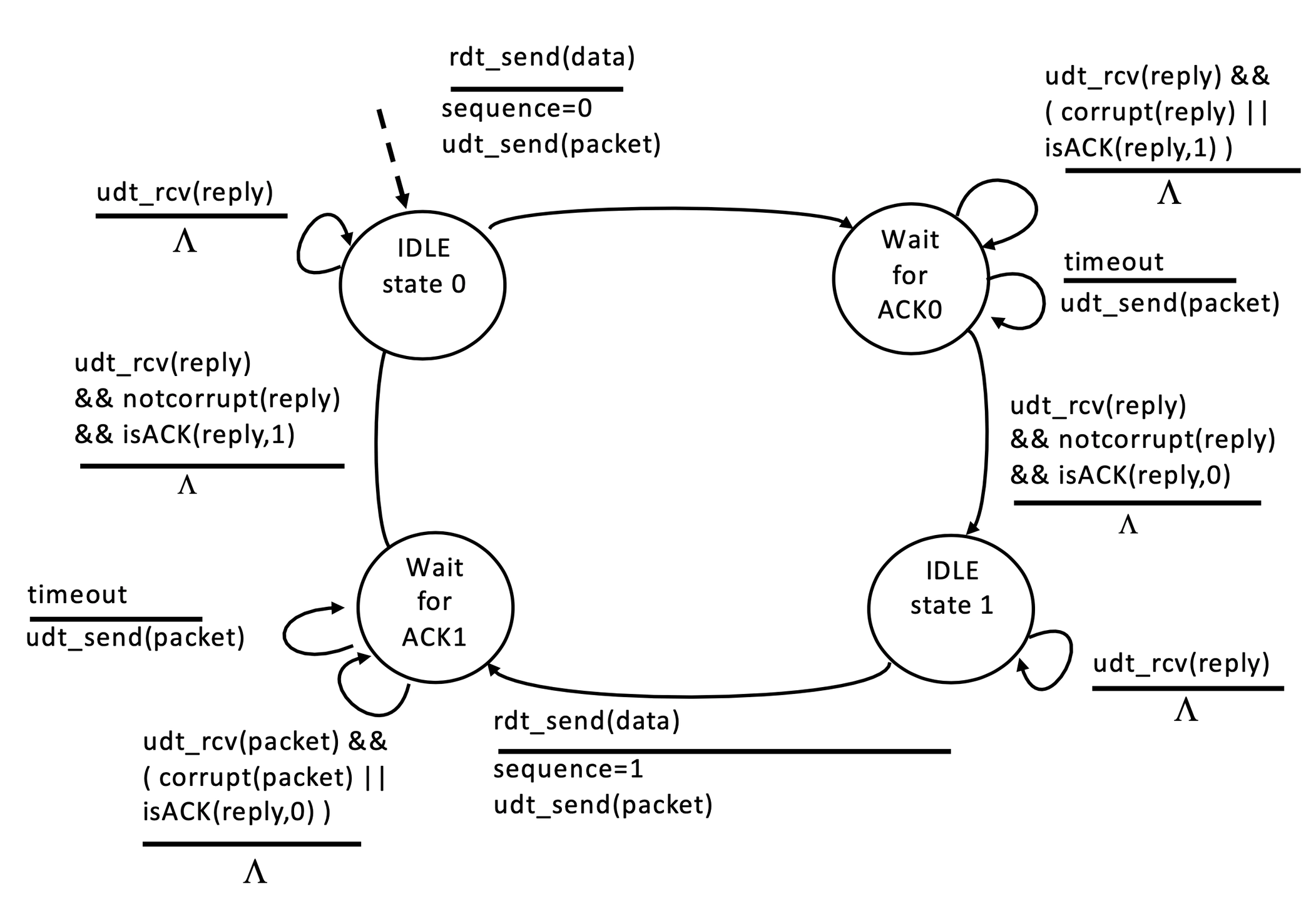
topRdt_send: set sequence number of packet
topRight: if a reply is mangled or wrong, we do nothing, but leave timer running
lowerTopRight: guess that receiver has not got packet and send again.
upperBotRight: correct reply so happy that the right packet has been received.
botRight: if we receive any ACK's just discard them as we aren't expecting any.
botRdt_send: same as other half, but with a seq #1 of 1.
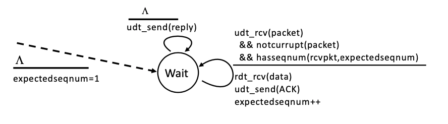
Receiver
Wait for #0 packet
same
udt_rcv(packet) && ( corrupt || hasSeq1 )
udt_send(ack)
next
udt_rcv(packet) && ( not_corrupt && hasSeq0 )
udt_send(ack) && rdt_rcv(data)
Wait for #1 packet: analogous
Solution to Performance Issues
Pipelined/PacketWindow protocols allow us to send multiple packets, before getting the ACK back (lots of packets in transit simultaneously).
Our window is a set of adjacent numbers, we have a sliding packet window which moves on during successful ACK. We have to limit the size of the window as any packet in the window must be stored in a buffer, so it can be resent when issues arise.
The back edge of our sender window is controlled by the last non-ACK'd packet.
Everything in the window is sendable
A window size n with last contiguous packet ACK'd being A: {A + 1, A+ 2, ... A + n}
where A + n + 1 can't be sent before A + 1 is ACK'd.
The back edge of our receiver window is controlled by last received packet, we can only accept packets with numbers IN the window (B + 1 undefined B + n) where B is the last contiguous received packet.
But we have two options for how we ACK:
Cumulative ACK - receiver sends ACK with number of Next In Order sequence number it expects. So our ACK for B + 4 will still be B + 1 until B + 1 is received.
Selective ACK- ACK individually acknowledges correctly received packets.
We have two general schemes of use:
Go Back N - uses cumulative ACK's and ONLY accepts packets in-order. If it receives any packet which is not in order it discards it.
rdt_send
if in window then send packet and increment seq number
otherwise buffer it and block.
timeout
resend whole window
success
update last received packet i.e back edge of window
anything but correct packet, send ACK of old i.e NAK. If correct, send correct ACK, accept data and move window.
😊 Simple to implement
😔 Perfectly good packets get thrown away on receive - causes lots of network congestion as one error resends WHOLE window.
Selective Repeat - uses selective ACK and allows receiver to accept out of order packets (as long as they are in window). Sender has a timer for EVERY packet sent and resends it (and only it) when packet timer runs out.
😊 don't throw away out of order packets
😔 takes a lot more space i.e. SACK mask for 127x2 outstanding packets is 8-16 bytes.
😔 hard to implement
From all this we see we CAN fully utilise a link with a high enough window size (governed by buffer size)
Throughput undefined n/RTT
Remember windows are ONLY for efficiency, situations exist where they don't help:
with low latency and low bandwidth a simple Automatic Repeat reQuest (ARQ) system would be fine without windows.
When connection is TERRIBLE, we are governed by packets being lost, NOT the ACK system.
When the user doesn't have much to send.
Transmission Control Protocol (TCP):
Format of TCP packets:
It obviously has source port, dest port, checksum and header length for all the same reasons as UDP.
Checksum: computed over its header and data (not whole packet).
We use sequence numbers which are the byte offsets from a file.
It represents which byte in the larger file the packet payload starts from, so they don't count in 1's but instead in ANY number (but commonly in Maximum sgement sizes = MTU - (IP header) - (TCP header)</u>).
We also start the sequence number from a random Initial Sequence Number to reduce Man in the Middle attacks.
We treat data transfer as a byte stream hence why our sequence number count in bytes.
There is a Must be Zero and an Urgent pointer which we ignore
There are also Flags and an Advertised Window to be discussed later.
Acknowledgments
We make TCP full duplex by having a sequence number (for the attached payload) and an acknowledgement (saying what has been received). It implements a form of Go Back N, so the acknowledgement number is always the NEXT byte it is expecting, but the receiver can buffer out of order packets (like selective repeat).
It implements a fast retransmit optimization which is triggered by k duplicate ACK's (k is normally 3). We immediately resend the required packet after k ACK's.
We fudge retransmission timeout based on the RTT estimation, which is an exponential averaging of previous RTT's.
Karn/Partridge algorithm says only sample RTT for original transmissions (not retransmissions) and sets undefined (variable in exponential averaging) to 0.875.
it says timeout value = 2 \* Est RTT, but uses exponential backoff when we don't have values to estimate from.
We don't include retransmissions because we could get the ACK for the original packet and then the RTT sample will be really small.
exponential averaging: undefined
Jacobson/Karels algorithm measures the deviation as well as using exponential averaging then timeout value = Est RTT + 4\*(Est Deviation). This is because deviation is caused by queuing time in routers.
often a linear deviation.
ensures that the tail probability of a spurious retransmission is small.
Initialising a TCP connection
We have host A wanting to speak to host B, they have to first synchronise ISN's as ports can be getting reused so we want to establish NEW connection.
It takes the form of a three way handshake:
SYN - A sends a packet with SYN flag and it's chosen ISN in seq #
SYN ACK - B sends a packet with SYN ACK flag with it's chosen ISN in seq # & A's ISN + 1 in ACK field.
ACK - A sends a packet with ACK flag with seq #1 = A's ISN and Ack# = B's ISN + 1
Note that the two ISN's wil be DIFFERENT, as we are setting up a channel for FULL duplex communication.
Losing SYN has large effect
We deal with SYN packets getting lost by setting an arbitrary timer to start (~3 seconds) and if we haven't got SYN ack by that point we send again.
Termination of connection
Normal termination, one side at a time
A send FIN
B send ACK (A's side of connection closed)
B send FIN
A send ACK
A could still receive another FIN from B if ACK is lost, so stays open a bit, then connection closed
Normal termination, both together
A send Fin
B send FIN ACK
A send ACK
Connection closes after a small wait period
Abrupt termination
A send RST (because application on A has crashed)
B doesn't need to ACK anything.
But A will continue to send RST anytime B sends it a message
as RST has not been sent reliably
Advertised window
the receiver indicates its window in its ACK's.
This helps with flow control - adjusting sending rate so we don't overwhelm receiver. The receiver advertises: W = B - (Last Byte Received - Last Byte Read)
W: window size
B: buffer size
Last byte received: RHS of buffer used
Last byte read: last byte of contiguous received
Stuff before this CAN still be in buffer it just need processing
The sender agrees to send no faster than W/RTT this means it can't overwhelm the receiver AND the receiver can adjust if things change.
We also do congestion control - adjusting sending rate so we don't overwhelm network
Due to our queuing system at routers we can delay packets and even drop packets when our network is busy. So we can't put too much load on the network or it becomes useless.
TCP solves this with end hosts adjusting their sending rates based on the implicit feedback from the network
We could do a far better job if routers told us the problem.
Jacobson's solution to congestion control
adapt our congestion window size in relation to network congestion we have to:
Discover available BW
Adjust to variations in BW
Share BW between flows
This is necessary to solve as:
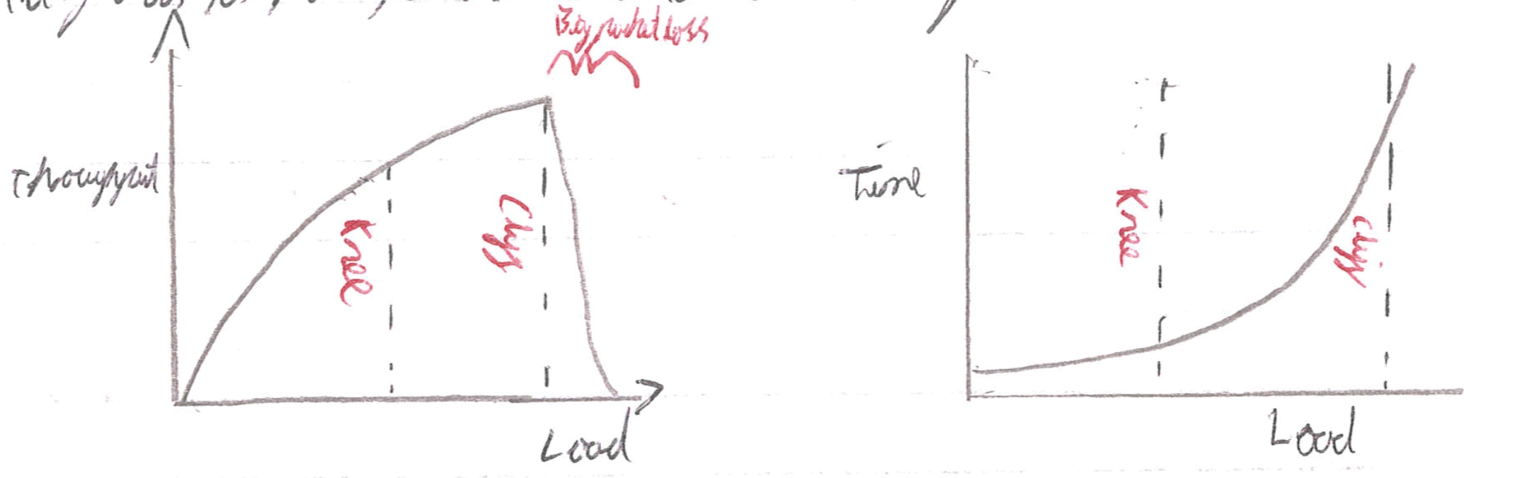
Basically the knee is the point where throughput is increasing slowly and delay increases fast and the cliff is when throughput plummets and delay goes to infinity.
General approaches:
Send Without care: the market will regulate itself DUDEEEE: leads to lots of lost packets
Reserve BW: pre-arrange BW allocations and enforce it, requires negotiation and gives low utilitisation of wire.
Pricing: who pays wins, packets bid against each other to not be dropped.
Dynamic adjustment: hosts get info about congestion (from network report or inferring) and adjust their level.
also have On-Off flow control: explicit messages from receiver to transmitter saying stop or go.
These message may be embedded in a layer: physical coding, DLL (PAUSE frames), etc.
Appropriate when delay has a constant and known range (bounding).
In TCP: we use dynamic adjustment and our ACTUAL window size is minimum of congestion window size and receiver advertised window size.
Bandwidth Discovery: done with slow start
start with CWND=1 (packet) then double CWND everytime we have an RTT without loss (the whole window comes back okay).
When we get our first loss we have an estimate of available BW.
Adjusting to BW variations: by oscillating around available BW using Additive Increase Multiplicative Decrease.
window size grows by 1 MSS (Maximum Segment Size) for every RTT without loss then on loss of packet we half the CWND.
This change is done when CWND = ssthressh (slow start threshold), which is an initially large number, that halves every time we get a loss undefined the first few saw teeth may be exponential.
Fact recovery: we grant credit for every duplicated ACK so that halving window doesn't mean everything grinds to a halt.
We enter fast recovery after 3 duplicate ACKs (seomtime we resend the packet).
We set CWND = old CWND/2 + 3.
Then every extra duplicate Ack we increment CWND as we are clearly still getting stuff through its just one packet was lost.
We leave fast recovery when we stop getting duplicate ACKs and return to normal
On timeout: we normally got to slow start and CWND to 1
since we have lost a packet AND we haven't been receiving duplicate ACK's so the rest ouf our packets probably aren't going through!
🤨 There are a variety of TCP flavours which do congestion control differently (with different constants and techniques) and the fact all of those interact means that analysing congestion is a NIGHTMARE.
Modelling TCP throughput
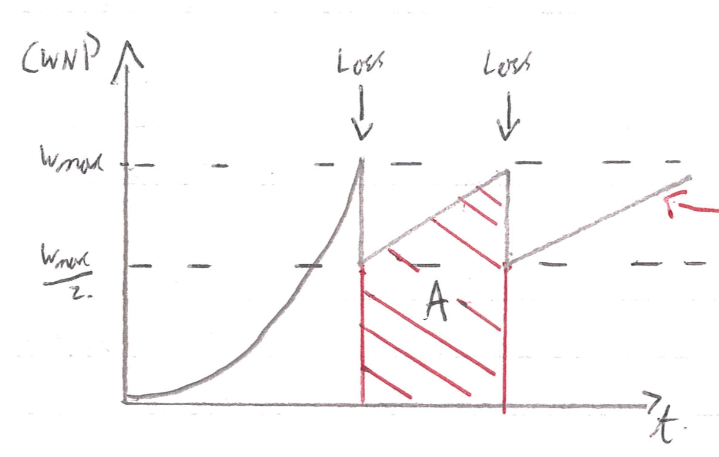
Left arrow: Note this increase is more like when steps when zoomed in: <img src="/notes/Computer Networking Notes.assets/Screenshot 2021-01-26 at 19.54.34.webp" alt="Screenshot 2021-01-26 at 19.54.34" style="zoom:25%;" />
undefined
undefined
A is the total data transferred, we do some maths with this and get:
Throughput = undefined undefined undefined
undefined: packet drop rate / probability of packet loss
Assumptions:
RTT is predictable and stationary. RTT may fluctuate at a short time scale, for example,
due to queueing delay.
The loss probability undefined is predictable. It can be dynamic depending on the level of congestion.
All loss indications must be exclusively triple dupACKs. TCP retransmission timeout leads to slow start, deviating from the "sawtooth" pattern.
Only the network is the bottleneck. The receiver may also throttle the rate with Flow Control.
😔
We can be misled by non-congestion related losses (receiver crashes)
We can fill up queues and just be delayed (during discovery)
Short flows may complete before discovering availabilty of capacity.
Using AIMD is impractical for highspeed links as we spend AGES building up ours speed.
Sawtooth discovery is choppy and some apps want a CONSTANT throughput
A hack here is to set your throughput according to estimates from previous equation (so we're TCP friendly), but don't chop about, just set at one speed.
Unfair under different Round Trip Times (throughput inversely proportional to RTT)
Tight coupling with reliability mechanisms (the window)
Endhosts can cheat
😯
1&2 could be solved: if routers tell endpoints of congestion
3-7 solved: if routers tell endpoints what rate to send at
8 solved: if routers enforce fair sharing
Elements of congestion control and why TCP isn't up to par.
Isolation/Fairness: TCP assumes good citizens
Adjustment: TCP is often slow in adjusting due to AIMD
Detecting congestion: TCP uses implicit feedback
Router Assisted Congestion Control
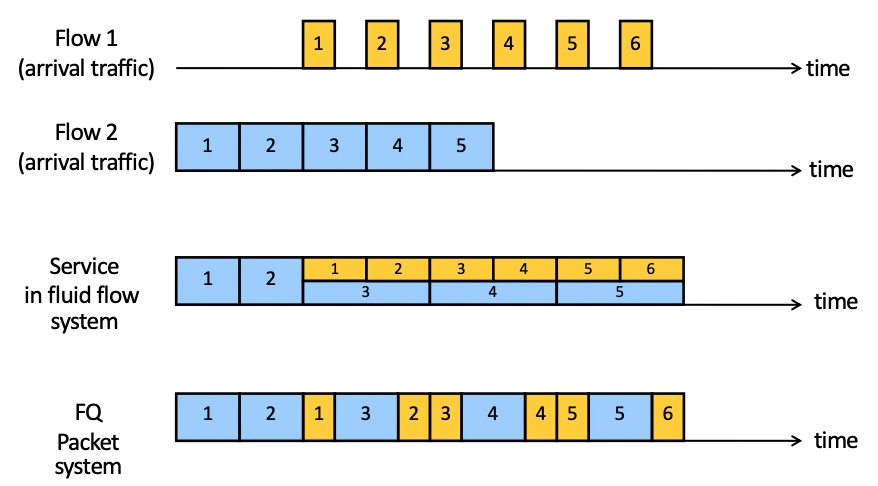
Fair Queuing tries to overcome some of the problems with TCP congestion control by getting routers to do some work!
Basic concept:
is that we compute the time at which the last bit of a packet would have left the router if were served bit-by-bit, then we serve packets in order of these calculated deadlines.
It is a generalisation of round robin queuing but with packets of varying sizes being handled in a fair manner.
😊
Isolation as cheating hosts don't get benefit
Bandwidth share doesn't depend on RTT
Flows can have any congestion control method they want
😔
More bookkeeping/work being done per flow and per packet in routers
undermines the connectionless assumptions of a packet-network such as the Internet (thereby breaking things like alternative path routing)
😯 It doesn't eliminate congestion, it just manages it!
🤨 Saying "this is fair" is difficult as what should be fair? If every flow gets equal BW, then there is incentive to make lots of flows to get greater control, seems weird doesnt it....
Explicit Congestion Notification: basically routers can set bits in packets to tell hosts that they're busy right now, then a host can treat that bit as a dropped packet and adjust accordingly.
😊 Don't confuse corruption with congestion (there are other reasons for packet loss)
😊 Can be an early indicator to get hosts to avoid delays
😔 Not used very much for historical reasons - some routers used to throw away packets with ECN turned on.
Application Layer
We often talk about communications getting into the client-server paradigm, where hosts are either:
Servers: always on with a permenant IP address
Clients: may be intermittently connected with dynamic IP address, which want to communicate with server (clients initialise connection).
DNS
For clients to talk to servers we have a human readable name which needs to be translated to an IP address, this is because we want:
To be able to map one name to multiple IP addresses (load balancing)
To be able to move our website to a new IP address, and still be accessible.
To have multiple names for the same website (.org and a .co.uk)
But we need to be able to translate between the two, so we need a Domain Name System. We manage it as a hierarchical database, where different domains (the.\*\*) are managed by different people with an unamed root at the top of the hierarchy commanding the whole thing.
We have Top Level Domain Servers for .co.uk etc and authoratative DNS servers which actually do the mappping and sit underneath the TLD's.
We actually have 13 root servers spread out across the world which are then further replicated by any-casting to have around 100 root servers.
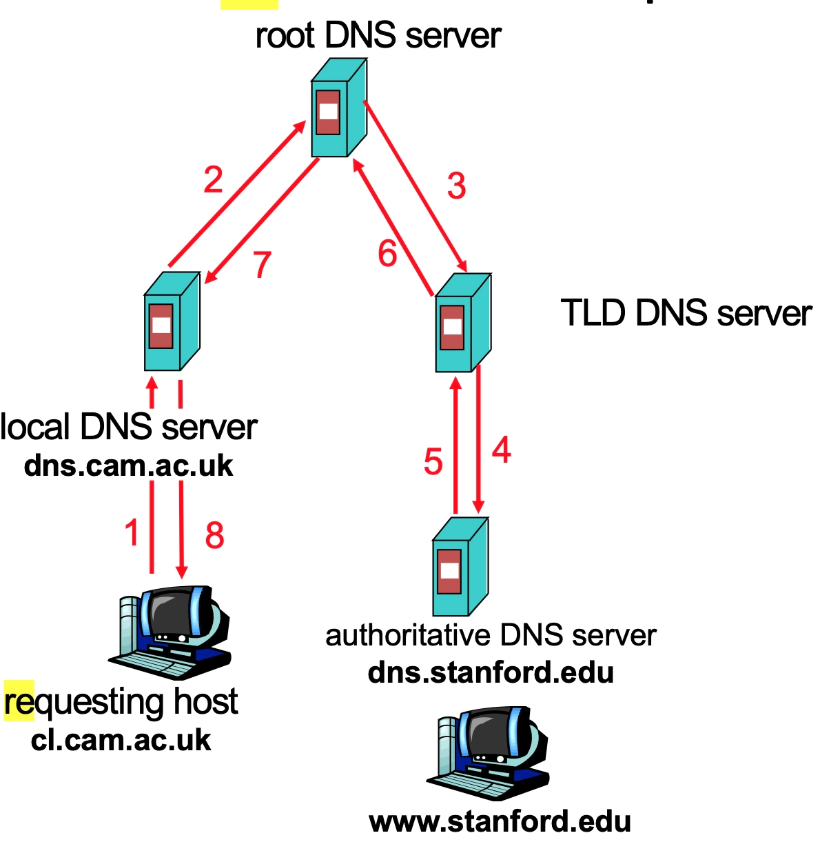
We use resolution: we don't directly ask these servers
Iterative resolution: we ask the local DNS serer for an IP.

The local DNS server (if it doesn't know) asks the root for the relevant next server to contact and then we ask the next and so on, until we get the authorative DNS server for the domain, which tells us the IP address.
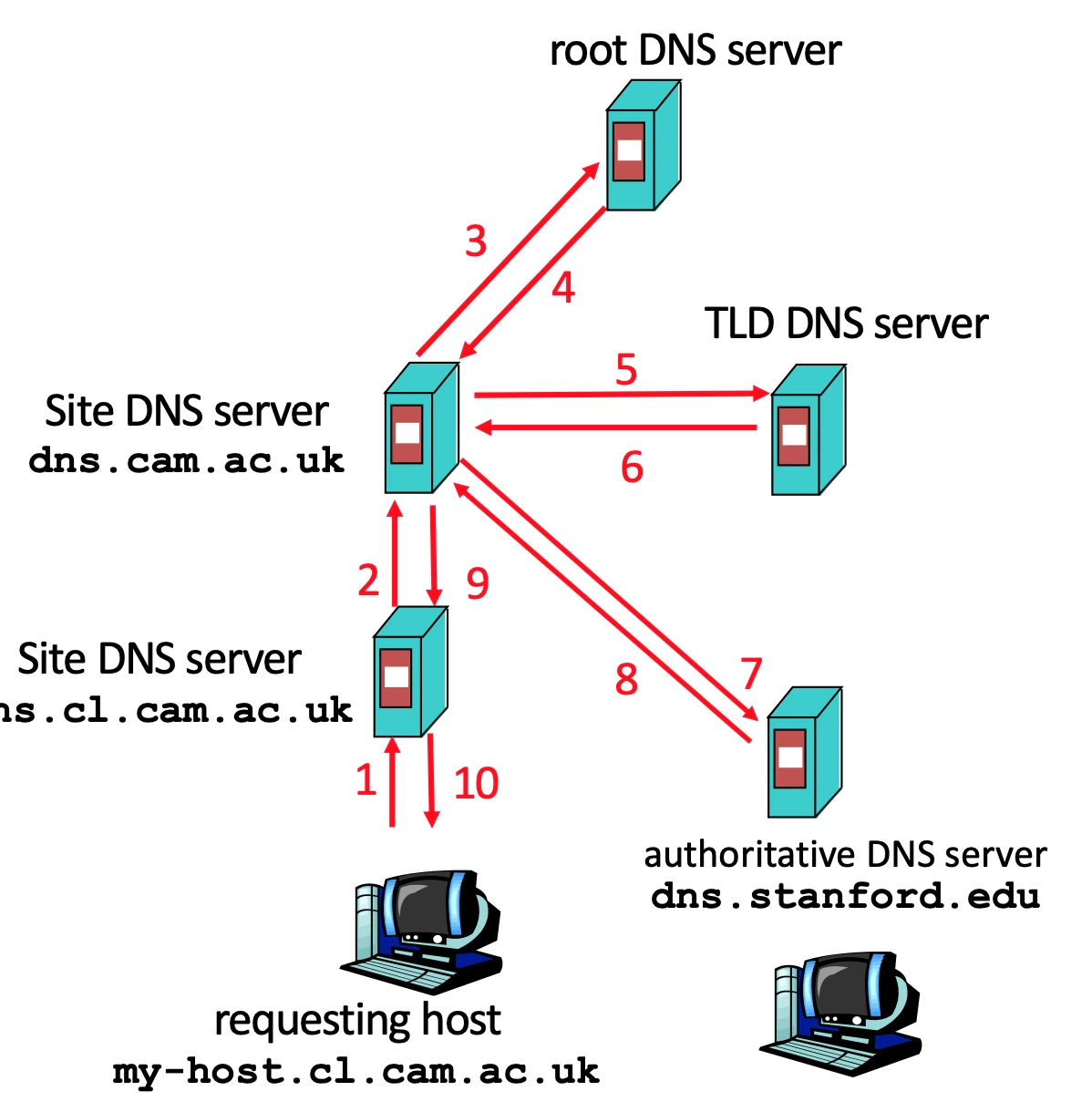
Recursive resolution: means the OTHER DNS servers do the work, so they recursively ask the next DNS server themselves.
😔 puts extra burden on root DNS server that it doesn't want.
😊 Iterative solutions do not permit any cache-advantage across multiple hosts making the same enquiry, while recursive does.
Hybrid resolution: means we use recursion INSIDE our organsiation, then use iterative OUTSIDE.
😊 most used system
Caching: necessary because fresh requests take a long time (increases availability as replica)
In the DNS servers they cache responses to common queries then they have a TTL field, which expires after a certain time so that the data does not go stale in our local DNS server.
Some servers also implement negative caches where they remember 'dud' domain names (especially common misspellings) which take time to fial. But this isn't often implemented.
Generally, DNS records do not frequently change, so a fairly large TTL is possible. However, if a record does change, the domain could be inaccessible for up to TTL time i.e. can handle that much time of downtime if Its change.
86400 seconds, or one day, is a good tradeoff.
With MX records they do not want any messages lost if their IP changes, so one day of downtime is unacceptable. As a result, the record expires after only 60 seconds, and is thus resolved almost every time an email is sent.
The nameserver record indicates which DNS server is authoritative for that domain
Reliability
Replication of servers (primary/secondary) - so that a name service (DNS for a domain) always has a server up - this also helps us load balance.
Use special UDP - we build on UDP as we want speed but we add reliability techniques so messages aren't lost.
If a request timeout ask a new server or exponential backoff
Each version of a query has same ID - as we don't care where the data comes from: all replicas should ALWAYS have same entries.
Increase availability by having name server on separate routable entities and/or mirrors.
Security: on its own isn't hugely secure
There is no verification of answers - there are many attacks (eg Man in the Middle) which could exploit this
Requires trust of local DNS server - we fundamentally have to trust the local DNS server to be 'a goodie'.
Cache poisioning - local records on a machine can be easily messed with.
DNSSEC: to provide message authentication and integrity verification wtih cryptographic signatures.
Does not:
Provide Authorisation
Provide Confidentiality
Protect against DDOS
We distribute keys via DNS, by building chains of trust from the root downwards, so parents sign the keys of their children.
World Wide Web
Internet includes email file transfer etc - anything could be transmitted.
Web - are some specific protocols for webpages etc.
We use Hyper Text Markup Language to describe web pages.
We use **Uniform Resource Locator ** to describe the names of pages:
protocol://hostname[:port]/directorypath/resource
protocol: http, ftp, https etc
hostname: DNS name or IP address
port: default to protocol's standard port
HTTP: used for most thing internet (Sending HTML files, JPG ...)
We send requests which are generally just headers in plaintext with
Structure: Message type - Host - UserAgent - ...
Where message type:
GET: this is asking for a certain file/bit of data in its entirety
HEAD: the same as GET, but only wants the header (so it can check content size, accessbiltiy, recent modifications etc)
POST: we submit stuff to the server (often from a form or something) to make something new.
PUT: we update or modify some information
Servers send responses:
Structure: A status line - A header - Some data
Where status line: generally contains protocol, status code and status message. Status codes:
1XX: information response
2XX: class of successful responses
200: just means 'ok', generally comes back with complete data requested
3XX: redirection messages about URI being elsewhere
4XX: class of Client Error Messages
400: says that we made a bad request
404: page not found
5XX: server error responses
500: internal server error
502: bad gateway
It is stateless by design
😊 Scalability of servers is easy as failure handling/out of order requests don't matter
😔 We need state!
We use cookies: an arbitrary string with some meaning to the server (e.g. DB index)
A client's first request asks for a cookie
The server responds with a cookie.
Every other client request sends that cookie with it, so servers can interpret the cookie to associate that client and send back the relevant information.
Performance
We note that a webpage needs multiple GET requests as we fetch HTML then images, CSS etc...
This means HTTP/1.0's stop & wait is very slow as each request does:
SYN, SYN ACK, ACK /w GET, Data, ACK
Solutions
Concurrent requests/responses - we open up multiple connections in parralel. We don't necessarily need to preserve ordering because it's stateless BUT it can screw the network (remember fair sharing??)
Pipelined Requests/responses - we use one TCP connection, but we batch requests (for the five different images or something)
Persistent connections - we maintain TCP connection across multiple requests (including transfers subsequent to HTML such as images/CSS)
Scorecard | Get n small objects undefined | Get n large objects undefined | General |
|---|---|---|---|
One-at-a-time | 2 _ n _ RTT | n(F/B) | SLOW |
Persistent | (n + 1) \* RTT | n(F/B) | Aggregates TCP overhead, but closing connections is hard |
M concurrent paths | 2 (n/m) \* RTT | (n/m)(F/B) | Bad for network |
Pipelined | 2RTT | n(F/B) | Sensible and takes advantage of TCP slow start |
Pipelined + Persistent | 2RTT + RTT after that | n(F/B) | Pretty good effort |
Get n small objects: dominated by latency
Get n large objects: dominated by bandwidth
Caching
cache at the client using if-modified-since
Reduce network use
We note that clients often transfer the same information, so we want to reduce server work.
We add an if-modified-since to our GET requests so the server replies:
Not modified if resource has not changed since requested time: (304)
The content if resource has changed (200)
Because of this we add two fields to response headers:
Expires - tells us how long to cache for
No-cache - tells us to ALWAYS ask server for recent version.
reverse proxies (by the content provider) to have a cache of static documents close to the server, which is what clients actually speak to.
reducer server work
forward proxies (by the ISP's) to have a cache of static documents near the clients in the ISP's server (Netflix!)
Reduce network use and server work
CDN: Content distribution networks (eg Akamai) to integrate forward and reverse proxies, we have caches all over the place with are fed by reverse proxies.
We even move some processing to these servers which handles
Dynamic Web Pages
Transcoding
Some Security
We have to add infrastructre all over the place, but its worth it and makes LOTS of cash.
We can do this with:
DNS entries
multi machines at many locations
an authoritative DNS for a page return IP address of a CDN server
URL rewriting
rewritten URL's point to specific CDN servers
Akamai
Anycast
multiple servers advertise same IP Address so most local routing achieved.
SPDY to HTTP/2 (from HTTP/1.1)
Binary protocol: so parsing and transport is more efficient and we have less errors.
Multiplexing using interleaving and persistance
Server push: becauser servers now need to GENERATE pages, we push static content (eg CSS or static JS) first, THEN push the HTML pages while page is built.
Header compression: we use gzip or some similar techniques to compress our headers.
Multi-hosting
Multiple sites on one machine: we have multiple server processess with different IP's or ports and then HTTP requests indicate site name in the required header.
😊 useful for web hosting companies.
Multiple machines for one site: we take advantage of address translation, so different DNS servers have different entries for some URL.
😊 helps to handle load and reduce latency
at one location: we only need one IP address, then use a load balancer to direct traffic to different machines (with one TCP connection always going to the same machine).
multiple locations: DNS is configured to return 'best' address
QUIC: Quick UDP Internet Connections, it throws away TCP and starts again
Does Reliable Transport over UDP - even though UDP is normally fire and forget
Uses Forward Error Correction
Does default crypto to reduce startup cost of TLS
we haven't spoken about this, but TLS has A LOT of startup cost as lots of things need to be agreed.
Offers restartable connections
Voice over IP
So up to this point we've basically just spoken about getting web pages, but we also want to send other data - VOICE/VIDEO 😳
In comes Session Initiation Protocol (that's right we have sessions, no longer stateless) to allow telephoning over internet:
User location
User availability
User capabilities
Session setup
Session management
It is just a application layer protocol, nothing wild, uses status codes and stuff similar to HTTP.
The key difference is we need resource reservation so we can be sure packets will reach destination fast enough.
This DOESN'T actually happen over wider internet, but it does still exist in local networks where we control the infrastructure so we guarantee reliability.
The other (more common) solution is to just use HTTP and accept some packets are dropped (losing one frame isn't the end of the world).
Peer to peer networking: there are some situations where we don't have an always on server, we just have peers with intermittent connection and changing IP addresses. We have three main situations for this.
File distribution (eg Bit Torrent or BBC iplayer 1.0)
The basic concept is that if our one server is sending N copies of a file to N machines the server does a lot of work.
Instead P2P has the server sending one copy and clients share the files around each other.
Time to distrbute file size F to N clients:
undefined: upload speed of server to each client
undefined: peer i download speed
undefined: peer i upload speed
Server-Client: undefined
1: the servers output speed onto network is limiting.
2: the slowest download speed
P2P: undefined
1: server upload file once
2: smallest download speed clients
3: total number of bits downloaded across network / (fastest upload rate is server + all clients).
Bit torrent
We have our tracker server which tracks participating peers and has the file.
It gives the list of peers to one of the clients
The torrent is the group of peers exchanging chunks (256kb pieces) of file.
We pull chunks by asking our neighbours for their chunks list and then asking for the chunks we're missing.
We then have a tit-for-tat where neighbours send chunks WHILE the neighbour gets chunks off of us.
If we give them less than they give us less.
We use a Distributed Hash Table to keep track of peers with a de-centralised DB. This has its complexities but we basically have each peer only aware of its two successors (when we have a circular DHT) to handle peer churn and finding appropriate data.
Skype: using peers as relays
We have a Skype login server to handle authentication, but comms use a hierarchical overlay with Super Nodes.
A super node is any computer which is routable and has good network connectivity.
We need them primarily due to NAT networks: as an outside peer cannot initiate a call to a peer inside the NAT (as it is not routable).
So the super nodes choose a relay node, which booth peers send data to, which can forward the info on.
The reason we need super nodes is to reduce server work of trying to direct calls. It is a nifty little use of P2P.